- 您现在的位置:买卖IC网 > Sheet目录237 > NSA5.0AT3G (ON Semiconductor)TVS ZENER 400W 5V SMA
�� �
�
�NSA5.0AT3G�
�MAXIMUM� RATINGS�
�Rating�
�Peak� Power� Dissipation� (Note� 1)� @� T� L� =� 25� °� C,� Pulse� Width� =� 1� ms�
�DC� Power� Dissipation� @� T� L� =� 75� °� C�
�Measured� Zero� Lead� Length� (Note� 2)�
�Derate� Above� 75� °� C�
�Thermal� Resistance� from� Junction� to� Lead�
�DC� Power� Dissipation� (Note� 3)� @� T� A� =� 25� °� C�
�Derate� Above� 25� °� C�
�Thermal� Resistance� from� Junction� to� Ambient�
�Forward� Surge� Current� (Note� 4)� @� T� A� =� 25� °� C�
�Operating� and� Storage� Temperature� Range�
�Symbol�
�P� PK�
�P� D�
�R� q� JL�
�P� D�
�R� q� JA�
�I� FSM�
�T� J� ,� T� stg�
�Value�
�400�
�1.5�
�20�
�50�
�0.5�
�4.0�
�250�
�40�
�?� 65� to� +150�
�Unit�
�W�
�W�
�mW/� °� C�
�°� C/W�
�W�
�mW/� °� C�
�°� C/W�
�A�
�°� C�
�Stresses� exceeding� Maximum� Ratings� may� damage� the� device.� Maximum� Ratings� are� stress� ratings� only.� Functional� operation� above� the�
�Recommended� Operating� Conditions� is� not� implied.� Extended� exposure� to� stresses� above� the� Recommended� Operating� Conditions� may� affect�
�device� reliability.�
�1.� 10� X� 1000� m� s,� non� ?� repetitive.�
�2.� 1� ″� square� copper� pad,� FR� ?� 4� board.�
�3.� FR� ?� 4� board,� using� ON� Semiconductor� minimum� recommended� footprint,� as� shown� in� 403D� case� outline� dimensions� spec.�
�4.� 1/2� sine� wave� (or� equivalent� square� wave),� PW� =� 8.3� ms,� duty� cycle� =� 4� pulses� per� minute� maximum.�
�ELECTRICAL� CHARACTERISTICS�
�(T� A� =� 25� °� C� unless� otherwise� noted)�
�Symbol� Parameter�
�I� PP�
�Maximum� Reverse� Peak� Pulse� Current�
�V� C�
�Clamping� Voltage� @� I� PP�
�I� F�
�I�
�I� R� V� F�
�V� RWM�
�I� R�
�Working� Peak� Reverse� Voltage�
�Maximum� Reverse� Leakage� Current� @� V� RWM�
�V� C� V� BR� V� RWM�
�I� T�
�V�
�V� BR�
�I� T�
�Breakdown� Voltage� @� I� T�
�Test� Current�
�I� F�
�V� F�
�Forward� Current�
�Forward� Voltage� @� I� F�
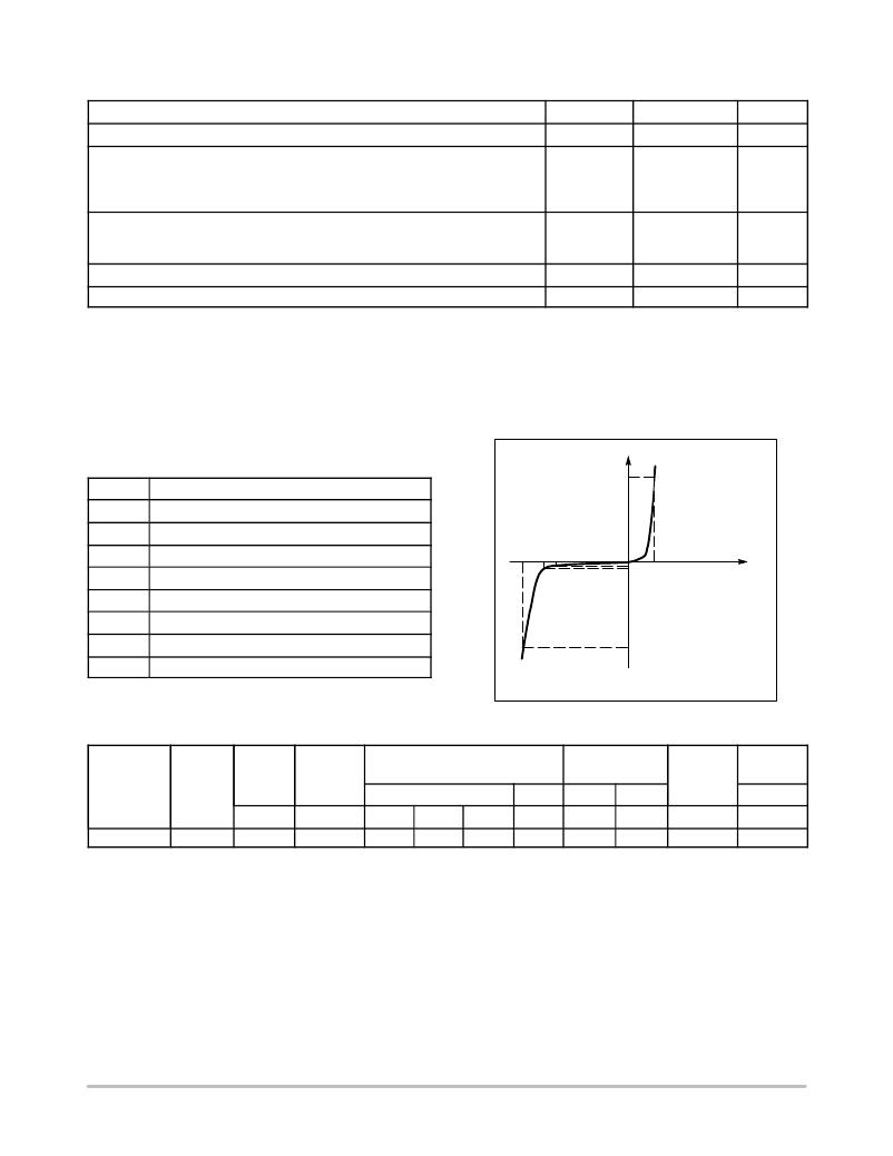
�I� PP�
�Uni� ?� Directional� TVS�
�ELECTRICA� L� CHARACTERISTICS�
�Device�
�Device�
�Marking�
�V� RWM�
�(Note� 5)�
�Volts�
�I� R� @�
�V� RWM�
�m� A�
�Breakdown� Voltage�
�V� BR� (Volts)� (Note� 6)�
�Min� Nom� Max�
�@� I� T�
�mA�
�V� C� @� I� PP�
�(Note� 7)�
�V� C� I� PP�
�Volts� Amps�
�C� Typ.�
�(Note� 8)�
�pF�
�V� F� @� I� F�
�(Note� 9)�
�Max�
�V�
�NSA5.0AT3G�
�QA�
�5.0�
�400�
�6.4�
�6.7�
�7.0�
�10�
�9.2�
�43.5�
�2450�
�3.5�
�5.� A� transient� suppressor� is� normally� selected� according� to� the� working� peak� reverse� voltage� (V� RWM� ),� which� should� be� equal� to� or� greater� than�
�the� DC� or� continuous� peak� operating� voltage� level.�
�6.� V� BR� measured� at� pulse� test� current� I� T� at� an� ambient� temperature� of� 25� °� C.�
�7.� Surge� current� waveform� per� Figure� 2� and� derate� per� Figure� 3.�
�8.� Bias� voltage� =� 0� V,� F� =� 1.0� MHz,� T� J� =� 25� °� C.�
�9.� 1/2� sine� wave� or� equivalent,� PW� =� 8.3� ms,� non� ?� repetitive,� I� F� =� 30� A.�
�http://onsemi.com�
�2�
�发布紧急采购,3分钟左右您将得到回复。
相关PDF资料
NSB12ANT3G
TVS ZENER 600W 12V SMB
NSB13ANT3G
TVS ZENER 600W 13V SMB
NSQA12VAW5T2G
TVS QUAD ARRAY LO CAP ESD SOT323
NUP1105LT3G
IC BUS PROTECTOR CAN/LIN SOT-23
NUP1301ML3T1G
IC DIODE ARRAY LOCAP ESD SOT-23
NUP1301U,115
IC DIODE ARRAY ESD SC-70
NUP2114UCMR6T1G
TVS ARRAY ESD 6-TSOP
NUP2201MR6T1
IC TVS DIODE ARRAY HS LINE 6TSOP
相关代理商/技术参数
NSA5050-3
制造商: 功能描述: 制造商:undefined 功能描述:
NSA5050-3C
制造商:MISCELLANEOUS 功能描述: 制造商:NUTS 功能描述:
NSA5060-4
制造商: 功能描述: 制造商:undefined 功能描述:
NSA5067-3-1
制造商:MONADNOCK(OTHER HDW) 功能描述: 制造商:NUTS 功能描述:
NSA5084-08
制造商:NUTS 功能描述:
NSA5319-02-018
制造商: 功能描述: 制造商:undefined 功能描述:
NSA5355-3ACL
制造商: 功能描述: 制造商:undefined 功能描述:
NSA5472-5K7
制造商:MISC. SPCR/STNDF/HND 功能描述: